


Parametric Block - Case #002
paramEtric BloCK - CasE 2
ARES Commander Custom Blocks make it possible to create intelligent elements whose size, position, or geometry can be modified through grips, parameters, and actions.
What makes this especially interesting is that the creation logic is practically the same as the one used for AutoCAD dynamic blocks. Learning this process therefore allows us to work with both platforms.
Note: Custom Blocks is the name given to parametric blocks in ARES Commander and DraftSight, while in AutoCAD they are called Dynamic Blocks. The steps explained in this tutorial for creating aparametric Custom Block in ARES Commander are essentially the same as those followed inAutoCAD to create a Dynamic Block.
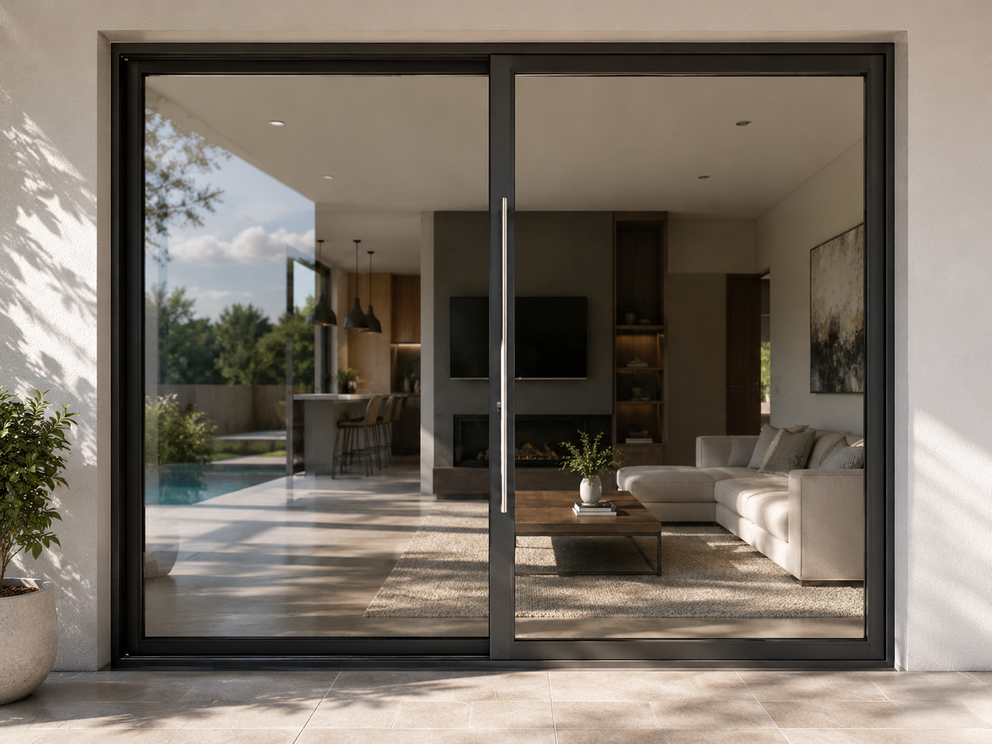
We have a drawing of a sliding door that we need to convert into a block.
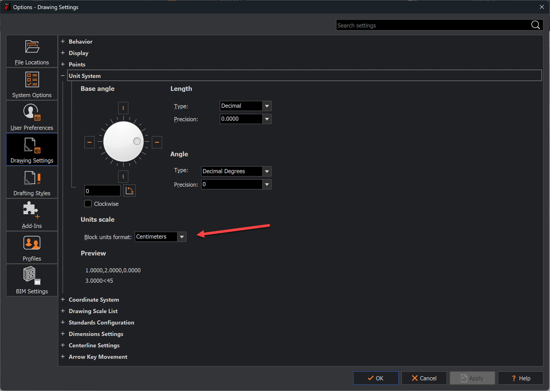
The first thing we do is check the drawing units. In this example in centimeters.

1. Create the Base Block
To create an intelligent block, we first need to create a conventional block.
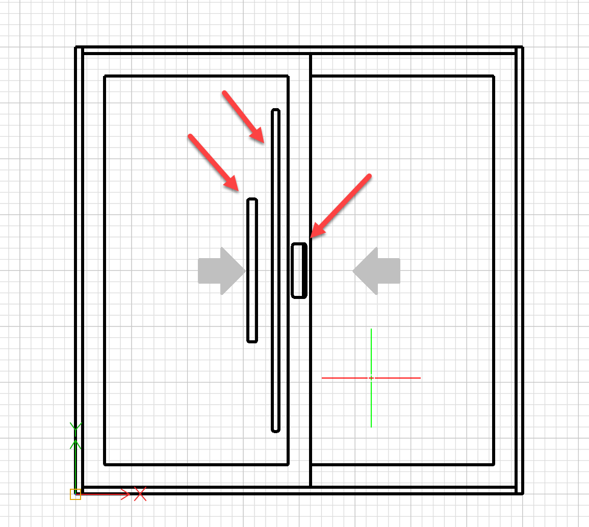
We begin by drawing the elements that represent a two-panel sliding door: the frame, the door panels, the central lines, and the arrows indicating the opening direction. To do this, we can use basic drawing and editing tools such as lines, polylines, rectangles, Trim, Extend, and others. Do not forget to check the drawing units. This is extremely important.

The UNITS command allows us to check this and adjust the units if necessary.
VIDEO 1
This step is not necessary, but I’ll take the opportunity to explain it.
To make the lines easier to see in the video, I’m going to assign a lineweight to layer “0”, which is where the existing entities are located. This is only to improve their visibility in the video.
ARES Commander allows you to easily turn the display of lineweights on or off. I change this property from the
Properties palette, in this case for the only existing layer. Remember that, whenever possible, it is recommended to create the entities of a block on layer
“0”. There are some exceptions, but we’ll cover those in another tutorial.
VIDEO 2
In this case, I have drawn three shapes that will be used to represent the three different types of pull handles recessed into the aluminum frame.

Ultimately, they represent three different states. In the video, you will see how I place them in their final position. Once positioned, the three shapes will be superimposed on top of one another.
Once we have all the elements ready, we create a simple block.
VIDEO 3
By double-clicking the simple block, it opens in the Block Editor, where we can edit it.
In this case, we want to move the three shapes to their final position. As mentioned earlier, for now they will appear superimposed on top of one another, which is why we chose simple shapes so that they remain easy to identify and work with.
VIDEO 4
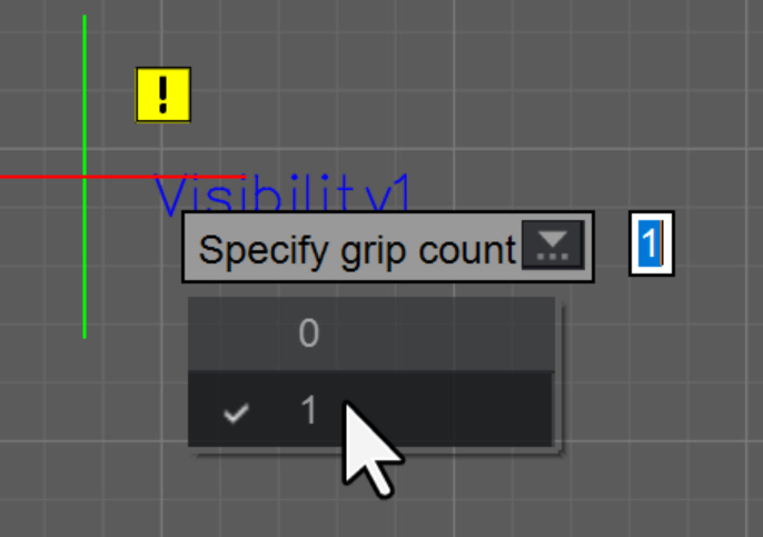
Now we select the Visibility element.
We click to specify where we want to place this grip.
From the drop-down menu, we select 1 so that it is visible, and then select the corresponding entities.

After saving the changes, we can test the block. See the video. The width and height now change correctly, although the behaviour of some other elements still needs to be improved.
VIDEO 5
In this example, we need three visibility states, which we will name:
- Option 1
- Option 2
- Option 3
These three icons are very important because they allow us to control whether the selected objects are visible or hidden.
The first icon lets us
display all visibility states at the same time, regardless of whether the objects are currently set as visible or hidden.
The other icons are used to show or hide specific elements depending on the selected visibility state.
See the video for the full process.
Basically, with Option 1 selected, for example, we choose which elements we want to show and which ones we want to hide.
In this example, I kept a fourth visibility state where all the elements can be seen at the same time.
This can be very useful in more complex situations, at least while the block is still being defined and adjusted. Once we have checked that everything works as expected, we can delete this extra visibility state.

From this point on, we are going to add parameters that allow us to modify the width and height of the door.
We already showed examples of how to configure these parameters in Case 1. The only difference here is that, if we want the visibility-controlled elements to move as part of another parameter, we also need to select the Visibility parameter together with the elements associated with it.
Note: If you have not seen the previous example yet (Case 1), click the link below to follow the process step by step: https://www.miltonchanes.de/parametric-block-case-1
As shown in the video, it is important to make sure that all elements from the different visibility states are displayed when adding them to an action.
If you do this while only one visibility state is shown, the elements belonging to the other states will not be included in the action.
There may be situations where this is exactly what you want, but that is
not the case in this example.
VIDEO 6
You don’t have ARES Commander, DraftSight, or AutoCAD? Don’t worry, you can download ARES Commander for free and try it out here. If you’re already an AutoCAD user and have never tried ARES Commander before, don’t worry—you’ll hardly notice the difference.
https://www.graebert.com/cad-software/download/ares-commander/