

Parametric Block - Case #001
paramEtric BloCK - CasE 1
ARES Commander Custom Blocks make it possible to create intelligent elements whose size, position, or geometry can be modified through grips, parameters, and actions.
What makes this especially interesting is that the creation logic is practically the same as the one used for AutoCAD dynamic blocks. Learning this process therefore allows us to work with both platforms.
Note: Custom Blocks is the name given to parametric blocks in ARES Commander and DraftSight, while in AutoCAD they are called Dynamic Blocks. The steps explained in this tutorial for creating aparametric Custom Block in ARES Commander are essentially the same as those followed inAutoCAD to create a Dynamic Block.
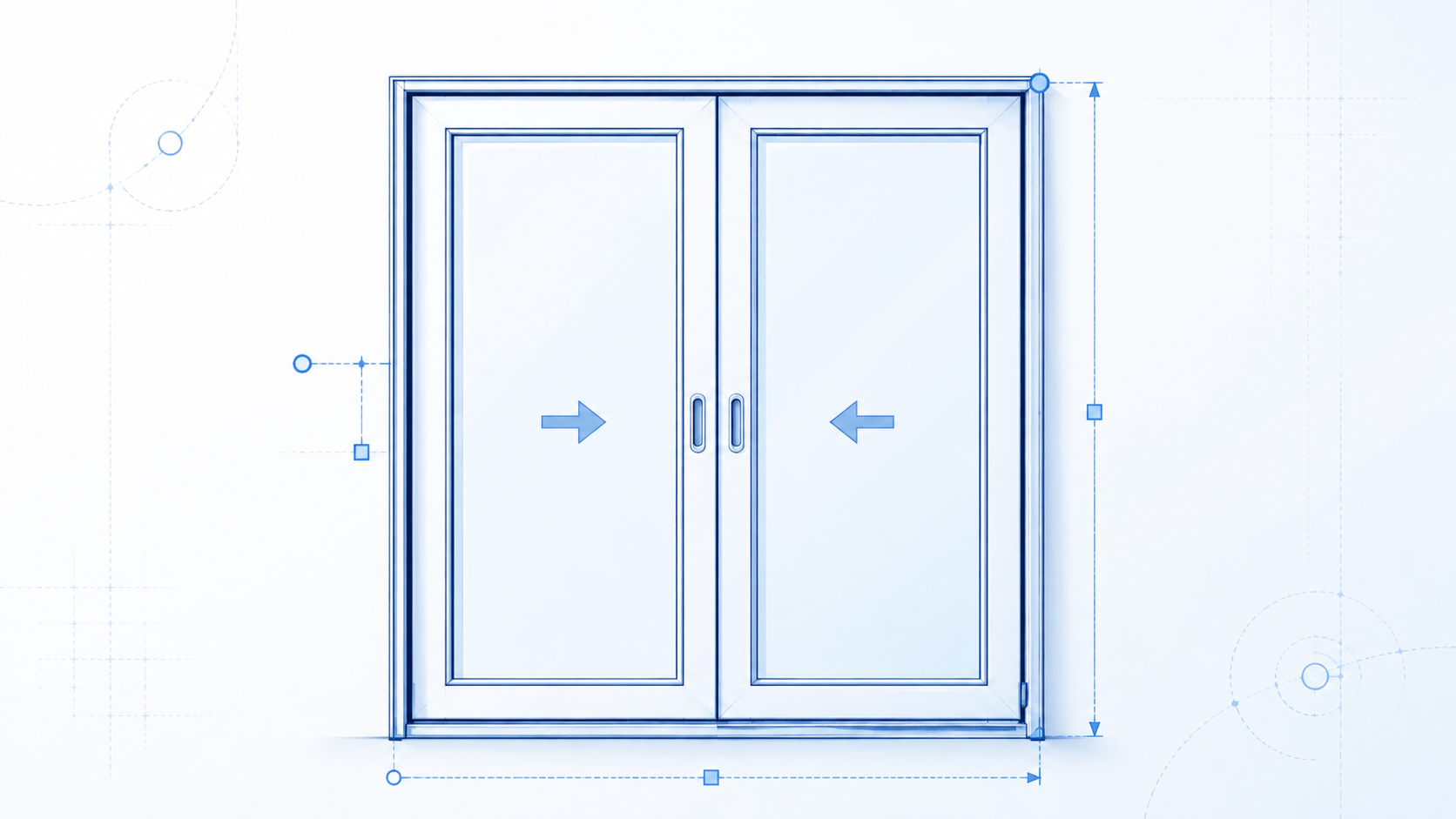
In this example, we will create a two-panel aluminium sliding door whose width and height can be modified directly through grips or from the Properties palette.

1. Create the Base Block
To create an intelligent block, we first need to create a conventional block.
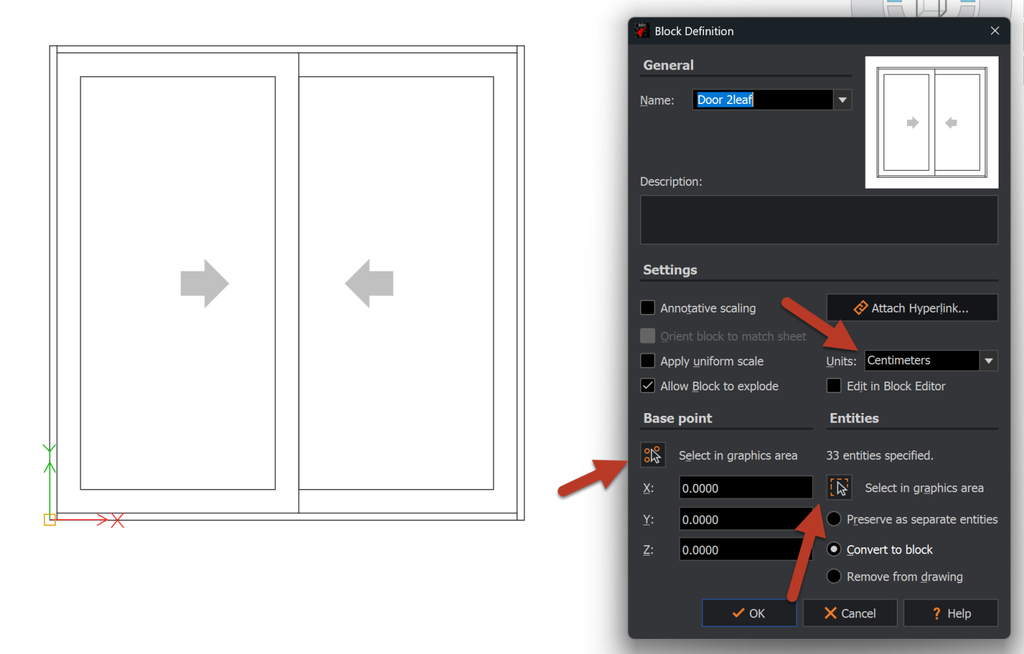
We begin by drawing the elements that represent a two-panel sliding door: the frame, the door panels, the central lines, and the arrows indicating the opening direction. To do this, we can use basic drawing and editing tools such as lines, polylines, rectangles, Trim, Extend, and others. Do not forget to check the drawing units. This is extremely important.
VIDEO 1
Once the geometry is complete, we create the block and open it in the Block Editor.
When creating the block, we assign a name and a description, define its insertion point, select all the entities that belong to it, and specify the correct units.
This ensures that when the block is inserted into another drawing that uses a different unit system, it will be scaled automatically.

Once the block has been created, we need to edit it. We can open it directly in the Block Editor by enabling the
Edit in Block Editor option, or simply double-click the block after creating it.
VIDEO 2
Inside the editor, we will find the tools that allow us to add a certain level of intelligence to the block.
This is, incidentally, the same basic concept used in software such as Revit when creating a parametric family.
2. Add the Width and Height Parameters
We add two linear parameters:
- One to control the width of the door.
- Another to control its height.
It is advisable to assign clear names to these parameters, such as
Width and
Height. This allows us to identify them easily in the Properties palette and enter exact values whenever necessary. Pay attention to the fact that we select the element called
Linear and configure it so that it has only one grip. This keeps one side of the block fixed.
VIDEO 3
The Linear element does nothing by itself. It simply defines a vector that can be used to control one or more actions.
It may have no grips at all when used for nested actions, or it may contain one or two grips. Two grips could be useful, for example, when we want to stretch an element in both directions.
In this example, we will use only one grip.

3. Configure the Stretch Action
There are many ways to add intelligence to a block, but we will begin with a simple operation: Stretch.
The Stretch action can be found in the Activities drop-down menu inside the Block Editor. See the video.
After selecting this action, we need to follow a series of steps. This requires becoming familiar with the command line, where the program requests each part of the process.
First, select the Linear element that we added previously. Because this element has two endpoints, we need to indicate which endpoint will control the action. Since we enabled only one grip, pressing Enter will automatically select the correct one.
Next, we must define:
- The area of the geometry that will be affected by the Stretch action. See the video.
- The entities that will participate in the Stretch action. See the video.
We repeat the same procedure for both the width and the height. See the video.
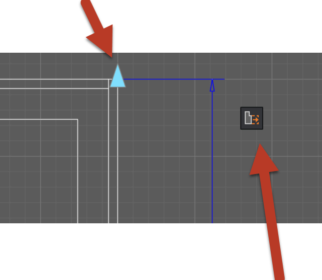
Actions associated with a parameter are represented by an icon.
When several actions are assigned to the same parameter, the corresponding icons appear next to one another. Each action can also be given a specific name, making it easier to remember what it does. See the video.

After saving the changes, we can test the block. See the video. The width and height now change correctly, although the behaviour of some other elements still needs to be improved.
VIDEO 4
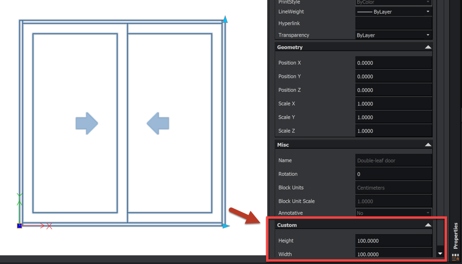
This is also a good opportunity to see that the values can be edited directly from the Properties palette. Because we assigned meaningful names such as Height and Width, the parameters are easy to identify and modify.
However, we can see that other elements, such as the central mullion and the opening arrows, have not moved. We will improve this next.
Note: The Reset Block option, which appears when right-clicking a selected block, simply returns that block instance to its original form before any changes were made using its grips. Each block instance is independent.
4. Keep the Arrows Centred
When we modify the width of the door, the arrows indicating the opening direction should also move so that they remain centred.
There is more than one way to achieve this. We could use Stretch, for example, but that would make the explanation more confusing. Instead, we will use the Move action because it is easier to understand.
In this case, we will associate a Move action with the grip that controls the horizontal dimension. We need the same grip to perform two actions at the same time:
- The Stretch action configured previously.
- The new Move action. See the video.
The process is as follows:
- Select the Move action.
- Select the relevant parameter, in this case the one controlling the horizontal dimension.
- Press Enter so that the action point is placed at the same location as the existing grip.
- Select the entities that need to move, in this case the two arrows.
VIDEO 5
Did you watch the video? We have a problem.
When the grip moves by 100 units, the arrows also move by 100 units. However, we need them to move by only 50% of that distance.
Fortunately, there is a simple solution.
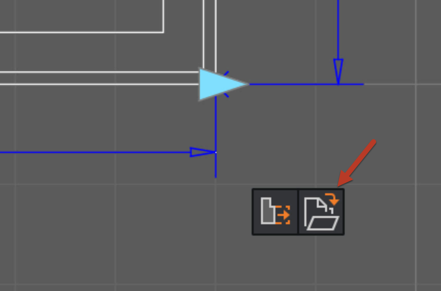
The solution can be found in the properties of the Move action. To access them, simply select the action by clicking its corresponding icon.

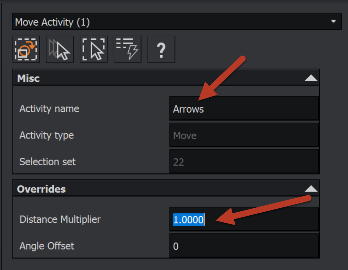
The properties of the Move action allow us to make several adjustments. Is the action name important? When you have several Move actions, they will automatically be called Move1, Move2, Move3, and so on. It can therefore become difficult to identify them. Assigning a descriptive name makes each action easier to recognise. This may not always seem necessary, but in a company where content is created for other people to reuse, it is better to be very strict and consistent with these details.
The property that is particularly important, and that you should remember, is Distance Multiplier. This property appears in many actions and solves a wide range of common problems.
In this case, we need to change its value to:
0.50
This means that when the grip moves by 100 units, this action will move the arrows by only 50 units because we have applied a multiplication factor of 0.50. As a result, the arrows will always remain centred relative to the total width of the door.

We test the block again, and the arrows now behave as expected.
VIDEO 6
5. Apply the Same Logic to the Height
We can repeat the same procedure for the height.
In some door blocks, arrows like these may remain at a fixed distance from the base.
However, in this example, we want them to remain vertically centred as well.
We therefore add another Move action associated with the height parameter and configure its Distance Multiplier as 0.50.
When the height of the door changes, the arrows will move by half the distance travelled by the grip, regardless of the direction in which the grip is moved.
VIDEO 7
6. Adjust the Central Section of the Door
We still need to configure the central section of the door correctly, particularly the mullion area.
In this case, using a Move action would not be appropriate because parts of the entities need to be stretched. It is therefore preferable to use another Stretch action, since the geometry needs to adapt to the new dimensions of the block.
Could we have used the original Stretch action?
The answer is no.
As with the arrows, the central section must respond to only 50% of the distance applied through the grip. We select the corresponding stretch area and the entities that need to be modified. Pay attention to the fact that some entities are selected using a Window selection and others using a Crossing selection. You can experiment with both selection methods and compare the results. After assigning the action, we select it and modify its Distance Multiplier property to 0.50, for the reasons explained previously.
The logic is the same: the central section must change by only half the distance travelled by the grip so that it remains correctly positioned and proportioned within the door.
Final Result
We can modify its width and height using the grips or by entering exact values in the Properties palette. The arrows remain centred, and the internal geometry adapts correctly to the new dimensions. This is a simple example, but it demonstrates one of the most important concepts when working with intelligent blocks:
A single grip movement can activate several actions at the same time.
When moving a grip, we can:
- Stretch part of the geometry.
- Move other elements.
- Apply different distance multipliers.
- Keep components centred or aligned.
The same steps and logic can be used to create a dynamic block in AutoCAD.
In addition, dynamic blocks created in AutoCAD can be used in ARES Commander, which makes it easier to work across both platforms.
Using this principle, we can develop windows, doors, furniture, profiles, construction details, and many other CAD elements capable of adapting automatically to different dimensions and situations.
VIDEO 8
We can also define minimum and maximum distances, as well as specific increments. For example, a block could increase in steps of 5 cm, or users could select from a list of predefined sizes such as 120, 130, and 140 when a manufacturer offers only those options. These are only a few of the many possibilities available.
You don’t have ARES Commander, DraftSight, or AutoCAD? Don’t worry, you can download ARES Commander for free and try it out here. If you’re already an AutoCAD user and have never tried ARES Commander before, don’t worry—you’ll hardly notice the difference.
https://www.graebert.com/cad-software/download/ares-commander/